
Ip67 Waterproof 4/5 To 1 T Solar Branch Connector For Solar Panel
Description
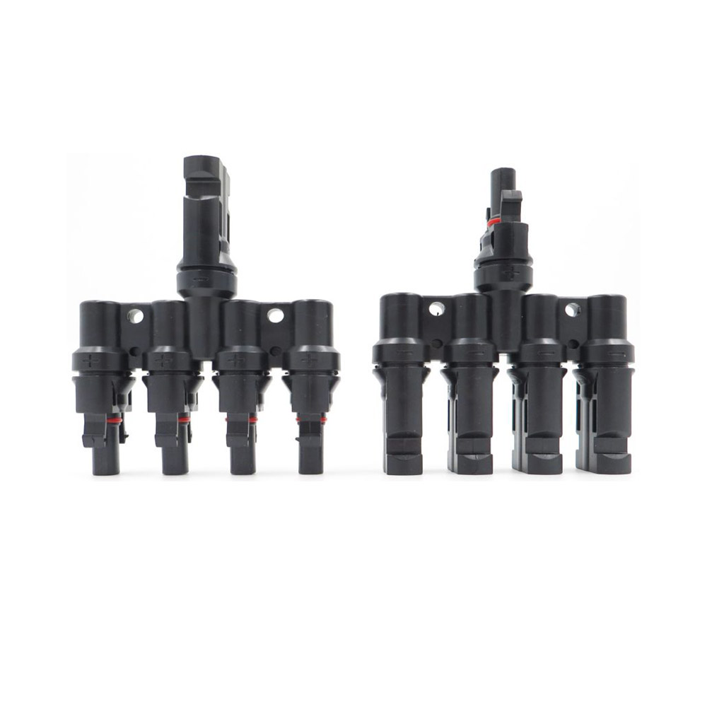
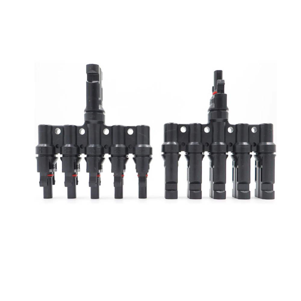
Solar branch connector is an innovative and convenient solution for those who want to connect multiple solar panels together. Rather than having to connect each panel individually, the branch connector allows for up to five panels to be connected at once, saving time and effort.
This product is made of high-quality materials that are durable and long-lasting. It can withstand harsh weather conditions and is resistant to corrosion and rust. This ensures that the product will continue to function efficiently and effectively for years to come.
In addition, the connector is very easy to install. It can be easily connected to the solar panels using simple tools .
Not only does the 4/5 to 1 T solar branch connector save time and effort, it also helps to optimize energy production. By connecting multiple panels together, the overall energy output is increased, which is great news for those who rely on solar energy to power their homes or businesses.
More Details
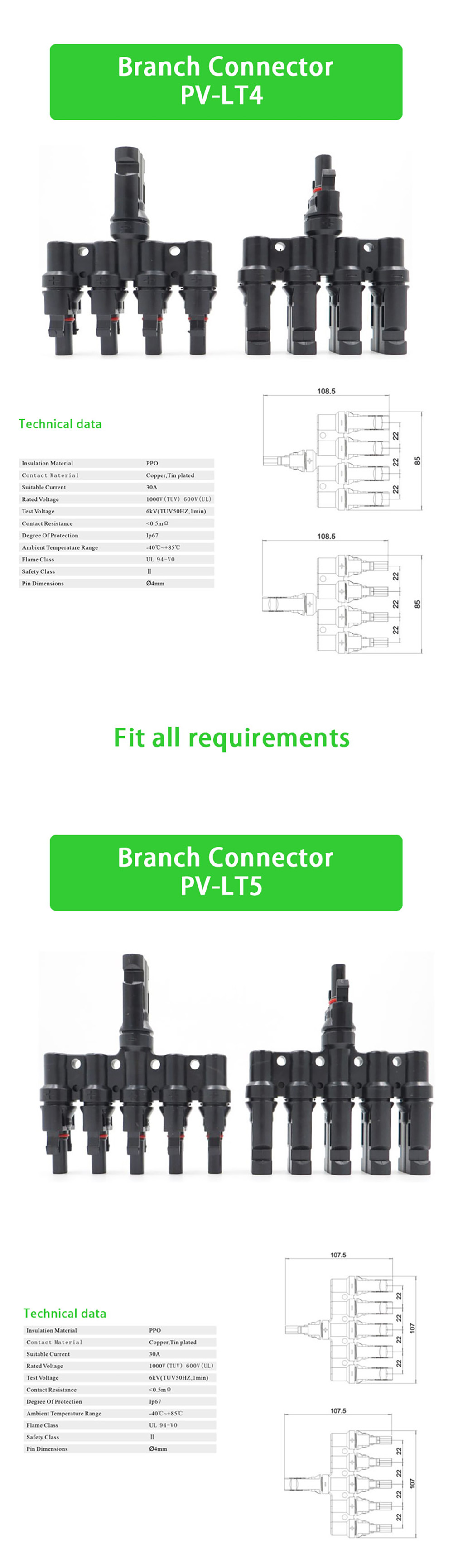
| Insulation Material | PPO |
| Pin Dimensions | Ø4mm |
| Safety Class | Ⅱ |
| Flame Class UL | 94-VO |
| Ambient Temperature Range | -40 ~+85 ℃ |
| Degree Of Protection | Ip67 |
| Contact Resistance | <0.5mΩ |
| Test Voltage | 6kV(TUV50HZ,1min) |
| Rated Voltage | 1000V(TUV) 600V(UL) |
| Suitable Current | 30A |
| Contact Material | Copper,Tin plated |
1. Why is your quotation higher than other suppliers?
In the Chinese market, many factories sell low-cost inverters that are assembled by small, unlicensed workshops. These factories cut costs by using substandard components. This results in major security risks.
SOLARWAY is a professional company engaged in R&D, manufacturing, and sales of power inverters. We have been actively involved in the German market for over 10 years, exporting around 50,000 to 100,000 power inverters each year to Germany and its neighboring markets. Our product quality is deserving of your trust!
2. How many categories do your power inverters have according to the output waveform?
Type 1: Our NM and NS series Modified Sine Wave inverters use PWM (Pulse Width Modulation) to generate a modified sine wave. Thanks to the use of intelligent, dedicated circuits and high-power field-effect transistors, these inverters significantly reduce power loss and improve the soft-start function, ensuring greater reliability. While this type of power inverter can meet the needs of most electrical equipment when power quality is not highly demanding, it still experiences around 20% harmonic distortion when running sophisticated equipment. The power inverter can also cause high-frequency interference to radio communications equipment. However, this type of power inverter is efficient, produces low noise, is moderately priced, and is therefore a mainstream product on the market.
Type 2: Our NP, FS, and NK series Pure Sine Wave inverters adopt an isolated coupling circuit design, offering high efficiency and stable output waveforms. With high-frequency technology, these power inverters are compact and suitable for a wide range of loads. They can be connected to common electrical devices and inductive loads (such as refrigerators and electric drills) without causing any interference (e.g., buzzing or TV noise). The output of a pure sine wave power inverter is identical to the grid power we use daily—or even better—since it does not produce the electromagnetic pollution associated with grid-tied power.
3. What are resistive load appliances?
Appliances such as mobile phones, computers, LCD TVs, incandescent lights, electric fans, video broadcasters, small printers, electric mahjong machines, and rice cookers are considered resistive loads. Our modified sine wave inverters can successfully power these devices.
4. What are inductive load appliances?
Inductive load appliances are devices that rely on electromagnetic induction, such as motors, compressors, relays, fluorescent lamps, electric stoves, refrigerators, air conditioners, energy-saving lamps, and pumps. These appliances typically require 3 to 7 times their rated power during startup. As a result, only a pure sine wave inverter is suitable for powering them.
5. How to choose a suitable inverter?
If your load consists of resistive appliances, such as light bulbs, you can choose a modified sine wave inverter. However, for inductive and capacitive loads, we recommend using a pure sine wave inverter. Examples of such loads include fans, precision instruments, air conditioners, refrigerators, coffee machines, and computers. While a modified sine wave inverter may start some inductive loads, it can shorten its lifespan because inductive and capacitive loads require high-quality power for optimal performance.
6. How do I choose the size of the inverter?
Different types of loads require different amounts of power. To determine the size of the inverter, you should check the power ratings of your loads.
- Resistive loads: Choose an inverter with the same power rating as the load.
- Capacitive loads: Choose an inverter with 2 to 5 times the power rating of the load.
- Inductive loads: Choose an inverter with 4 to 7 times the power rating of the load.
7. How should the battery and inverter be connected?
It is generally recommended that the cables connecting the battery terminals to the inverter be as short as possible. For standard cables, the length should be no more than 0.5 meters, and the polarity should match between the battery and the inverter.
If you need to increase the distance between the battery and the inverter, please contact us for assistance. We can calculate the appropriate cable size and length.
Keep in mind that longer cable connections can cause voltage loss, meaning the inverter voltage may be significantly lower than the battery terminal voltage, leading to an undervoltage alarm on the inverter.
8. How do you calculate the load and working hours required to configure the battery size?
We typically use the following formula for calculation, though it may not be 100% accurate due to factors like the condition of the battery. Older batteries may have some loss, so this should be considered a reference value:
Work hours (H) = (Battery capacity (AH)*Battery voltage (V0.8)/ Load power (W)

Products categories
-

2500W DC to AC Power Inverter 12V/24V/48V To 11...
-

600W To 3000W Pure Sine Wave Inverter With Buil...
-

600W 12 Volt 24 Volt DC to AC 110 Volt 220 Volt...
-
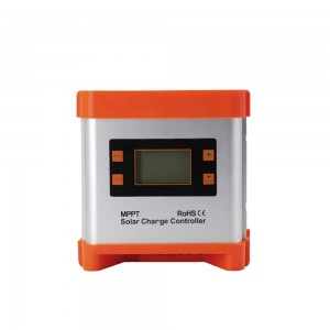
12V/24V 10A 20A 30A Mppt Solar Charge Controller
-
12V/24V/48V 40A 50A 60A Mppt Solar Charge Contr...
-
600w 1000w 1500w Usb Type-C Dc Ac Output Emerge...